Does counter electrode (CE) size matter?
Aug 16, 2021
Article
 Share via email
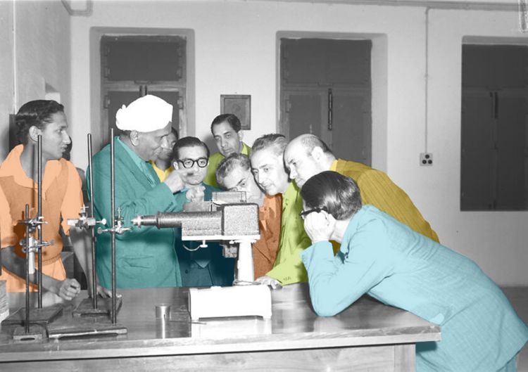
To begin, let’s go back to the year 1950 when metallurgists and chemists tried to shine a light on a fascinating electrochemical phenomenon originally discovered in the 17th century by the chemist Sir Humphry Davy [1].
 was credited with many discoveries in the field of electrochemistry.")
If you dip a wire made of iron (or as electrochemists say: an iron electrode) into diluted sulfuric acid (which is considered the electrolyte), it instantly starts to dissolve—it corrodes. If you then insert another electrode which does not corrode (e.g., platinum), and connect the iron electrode to the negative pole of a current source, and the platinum wire (electrode) to the positive pole, the iron dissolution will slow down or even stop, depending on the voltage applied.
On the other hand, if you connect the iron electrode to the positive pole and raise the voltage from very low values to higher ones, the dissolution grows exponentially with the increasing voltage.
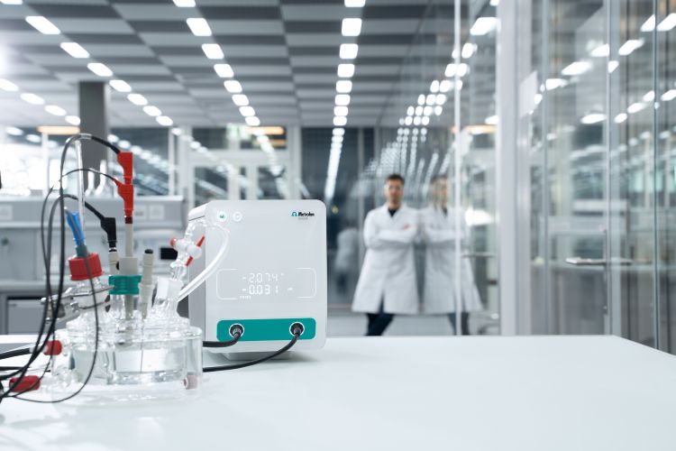
However, above a certain current limit (and depending on the electrode area, electrolyte composition, and temperature), the current suddenly drops to very low values, and the iron electrode stops dissolving. This phenomenon was detected by Michael Faraday, and he called it «passivation». This phenomenon has been subject of controversy and disputes until the 1950's when a better understanding was possible with the invention of the modern potentiostat (Figure 1).

In experiments where the ohmic drop may be high (e.g., in large-scale electrolytic or galvanic cells or in experiments involving nonaqueous solutions with low conductivities), a three-electrode electrochemical cell is preferable. In this arrangement, the current is passed between the working electrode (WE) and a counter (or auxiliary) electrode (CE).
Learn more about the ohmic drop in our free Application Notes.
Ohmic Drop Part 1 – Basic Principles
Ohmic Drop Part 2 - Measurement

The counter electrode can be made of any available electrode material because its electrochemical properties do not affect the behavior of the working electrode of interest. It is best to choose an inert electrode so that it does not produce any substances by electrolysis that will reach the working electrode surface and cause interfering reactions there (e.g., platinum or carbon). Because the current flows between the WE and the CE, the total surface area of the CE (source/sink of electrons) must be larger than the area of the WE so that it will not be a limiting factor in the kinetics of the electrochemical processes under investigation.
Sometimes it is placed in a compartment separated from the working electrode by a sintered-glass disk or other separator (Figure 2). Bulk electrolysis experiments typically require much longer times than electroanalytical experiments, so separation of the counter electrode is required.
The potential of the working electrode is monitored relative to a separate reference electrode (RE), positioned with its tip nearby (with a Luggin capillary as shown in Figure 3). The potentiostat used to control the potential difference between the working electrode and the reference electrode has a very high input impedance so that a negligible current flows through the reference electrode. Consequently, the potential of the reference electrode will remain constant and equal to its open-circuit value. This three-electrode arrangement is used in most electrochemical experiments.
The counter electrode is used to close the current circuit in the electrochemical cell. It is usually made of an inert material (e.g., Pt, Au, graphite, or glassy carbon) and it hosts a redox reaction which occurs at the CE surface that balances the redox reaction at the surface of the WE. The products of this reaction can diffuse to the WE and interfere with the redox reaction occurring at that site. However, in electroanalytical experiments such as cyclic voltammetry (CV), the time scale of the experiment is too short for this diffusion to be able to cause significant interferences. Therefore, in most cases there is no need to place the CE in a separate compartment, as shown in the electrochemical cell in Figure 3.

The potential profile in an actual cell depends on the electrode shapes, geometry, solution conductance, and more. If the reference electrode is placed anywhere except precisely at the electrode surface, some fraction of an uncompensated potential, iRu (due to the uncompensated resistance, Ru) will be included in the measured potential. Even when the tip of the reference electrode is designed for very close placement to the working electrode by use of a fine tip (Luggin capillary, also known as a Luggin-Haber capillary), some uncompensated resistance usually remains. Modern electrochemical instrumentation includes circuitry for electronic compensation of the iRu term [2].
Get a basic overview of the proper electrochemical cell setup in our free Application Note.
As mentioned earlier, the electrochemical reaction of interest takes place on the working electrode, and the electron transfer there will generate the measured current which flows between the WE and CE. As a general rule for accurate current measurements and an unhindered flow of electrons in the cell, the counter electrode should be three times larger than the working electrode. The kinetics of solvent electrolysis are generally slow, so the only way to ensure the CE reaction can sustain the required cell current is to significantly increase the surface area (e.g., with Pt gauze or a Pt rod/sheet).
However, in poorly conductive media (or high currents), when positioning the counter electrode in the cell (i.e., for the cell geometry), it is worth considering where the field lines between the WE and CE will go, and whether the WE will experience a uniform field. It is generally recommended to move the counter electrode away from the working electrode, or even to put it behind a separator, unless you are certain that the WE reaction is insensitive to pH. The CE reaction sustains the current flow, but it is often unknown exactly what kind of reactions are occurring at the counter electrode. For most aqueous electrochemistry experiments this is likely to be solvent electrolysis, which leads to a change in the pH.
When the application requires, the potential of the counter electrode can be monitored during the experiment with the S2 electrode of VIONIC. Find out more in our free Application Note.
Measuring the potential at the counter electrode with VIONIC powered by INTELLO

Alternative counter electrode materials
Platinum is expensive, and it is too costly to use for large CE areas. Suitable alternative electrode materials include nickel-based alloys or carbon. Be aware that nickel-based alloys may passivate, and carbon will be oxidized at high potentials of the CE. Therefore, those materials should have a sufficient area to avoid strong polarization.
Platinized titanium is a good choice when larger counter electrode areas are required. Platinized titanium is produced either in the form of sheets or mesh grids. Mesh grids (Figure 4) have very desirable properties: a large active area compared to the geometric area, and the electrolyte is able to flow through the counter electrode.
Also, at the counter electrode, a voltage drop occurs across the metal-electrolyte interface. To reduce this drop, it may be useful to use platinum covered with platinum black to increase the roughness, and consequently, the active surface area.
Final notes
Size matters in typical electrochemical measurements. Larger counter electrodes create an unconstrained current flow between WE and the CE, leading to more stable and insightful experiments. It is equally important that the overall cell configuration provides the required current density distribution. Thus, a counter electrode of the same size as the working electrode, mounted parallel to it, may optimize the current distribution without significant adverse effects from the size of the counter electrode.
The reaction occurring at the CE should be fast so that the potential drop between the counter electrode and the electrolyte does not limit the polarization that can be applied.
The products of the reaction occurring at the CE should not contaminate the solution. In practice, there will always be an electrochemical reaction at the counter electrode, and the products of that reaction should be harmless or able to be easily removed. Inert electrodes such as platinum or graphite are often used, in which case the reaction products are usually gases (oxygen or chlorine when anodic, or hydrogen when cathodic) that can be removed by bubbling air or nitrogen past the counter electrode (although there may also be a pH change at the CE).
Your knowledge take-aways
References and suggested further reading
[1] Knight, D. Humphry Davy: Science and Power (Volume 2 of Cambridge Science Biographies); Cambridge University Press: Cambridge, UK, 1998.
[2] Bard, A. J.; Faulkner, L. R. Electrochemical Methods: Fundamentals and Applications, New York: Wiley, 2001, 2nd ed. Russian Journal of Electrochemistry, 2002, 38, 1364–1365. doi:10.1023/A:1021637209564
[3] Yang, W., Dastafkan, K., Jia, C., et al. Design of Electrocatalysts and Electrochemical Cells for Carbon Dioxide Reduction Reactions. Adv. Mater. Technol. 2018, 3, 1700377. doi:10.1002/admt.201700377
[4] Cottis, R. A. 2.30 – Electrochemical Methods. In Shreir’s Corrosion; Cottis, B., Graham, M., Lindsay, R., Lyon, S., Richardson, T., Scantlebury, D., Stott, H., Eds.; University of Manchester: Manchester, UK, 2010; Vol. 2, pp 1341–1373. doi:10.1016/B978-044452787-5.00068-8
[5] Vanýsek, P. Impact of electrode geometry, depth of immersion, and size on impedance measurements. Canadian Journal of Chemistry 1997, 75(11), 1635–1642. doi:10.1139/v97-194